Spatial Robot Programming
An AR simulator for learning how six-axis industrial robots move and are programmed.
Training without taking a robot offline
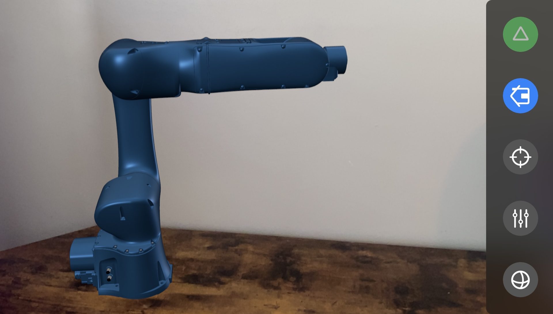
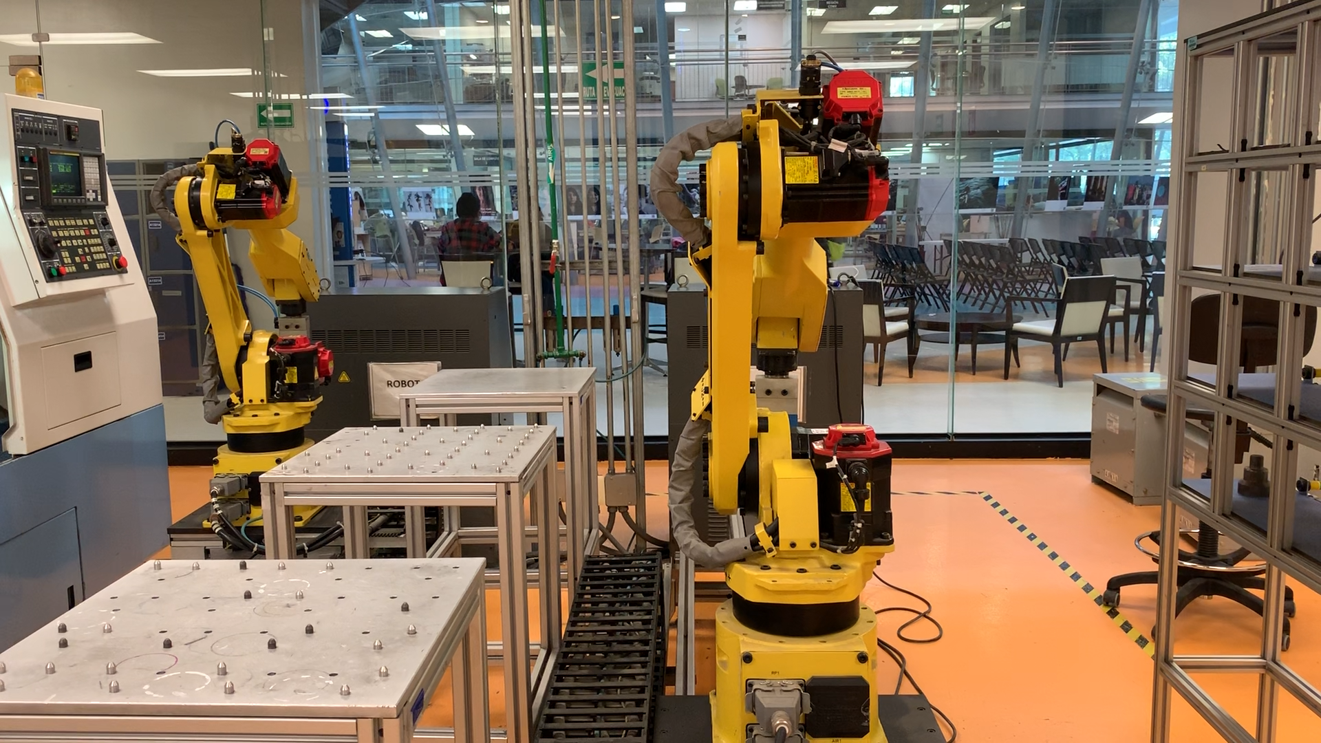
Training on an industrial robot is expensive, access is limited, and practice can interrupt production. Desktop simulators reduce that burden, but robot programming is fundamentally spatial: operators must understand how joints, tool orientation, reach, and the surrounding workspace relate to one another. This prototype uses AR to place a six-axis robot in the room, giving trainees a way to practice those relationships without reserving a physical machine or putting hardware at risk.
Place, pose, and practice
Surface detection anchors the model to the room. The robot can then be positioned, rotated, and inspected at scale. A compact teach pendant lets an operator practice three parts of robot programming:
- Joint mode — Learn how each of the six axes changes the robot's pose within its operating range
- World mode — Move the tool through x, y, z, roll, pitch, and yaw while the simulator resolves the joint configuration
- Routine mode — Save end-effector positions as waypoints and replay them as a simple program
Every command produces a spatial result
Tracking, controls, kinematics, and rendering operate as one feedback loop. Each command becomes an immediate simulated movement in the room, allowing the operator to connect pendant input with the resulting joint configuration and tool position.
ARKit anchors the robot to a detected surface at scale.
The operator enters a joint change, tool step, or waypoint.
Custom kinematics converts the command into a six-joint state.
RealityKit animates the result in the surrounding workspace.
A working model of the machine
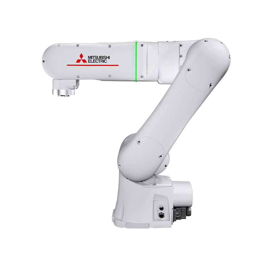
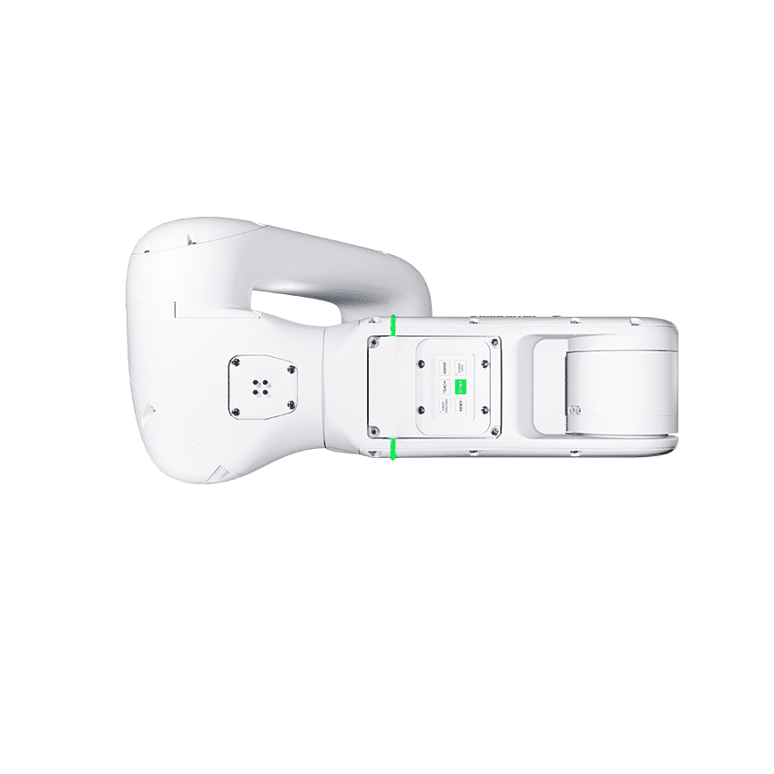
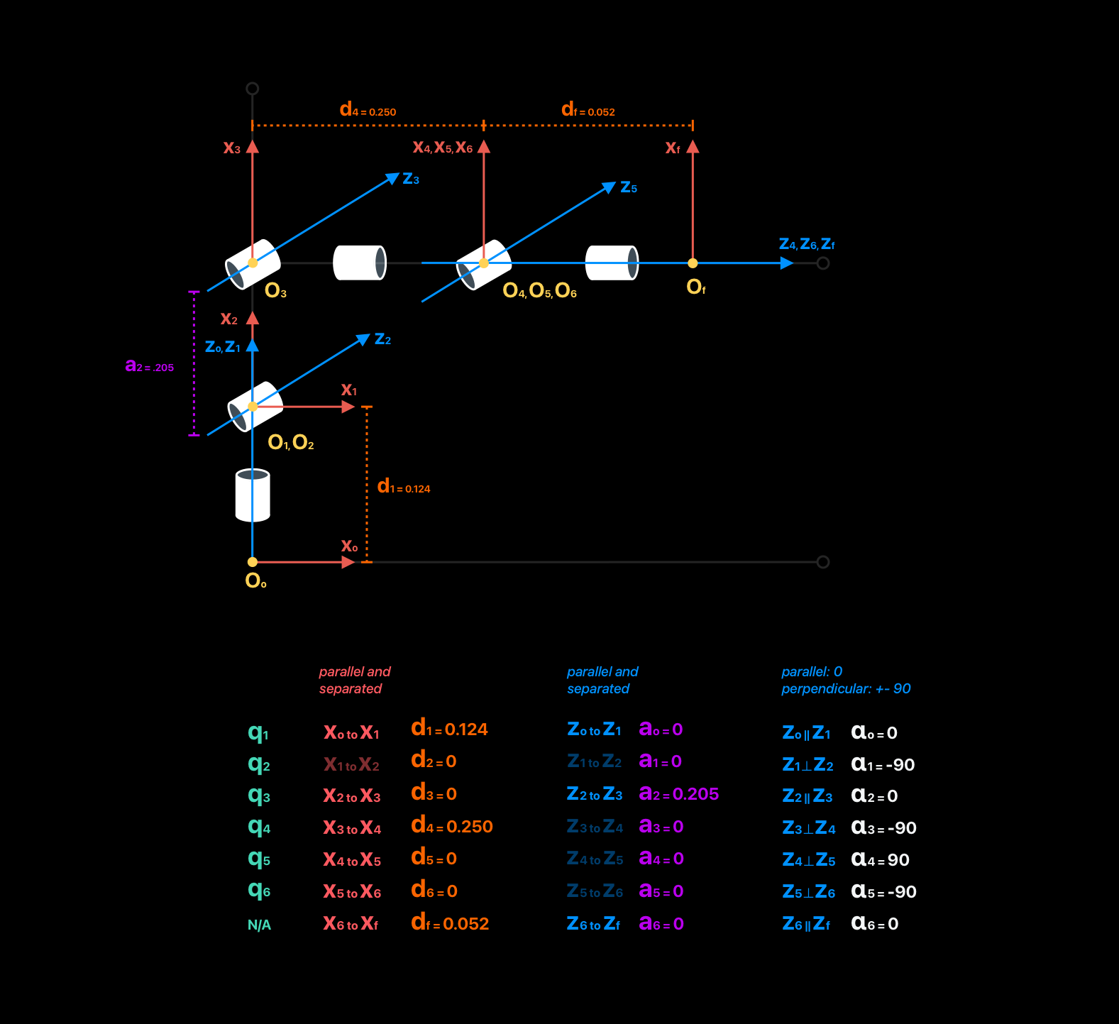
The prototype is based on the Mitsubishi MELFA ASSISTA RV-5AS (specifications). Mechanical drawings and the original CAD assembly were translated into seven linked USDZ parts. A data-driven robot definition stores each pivot, rotation axis, operating range, and Denavit–Hartenberg parameter. RealityKit uses that definition to assemble the model and preserve the movement of the physical mechanism.
From notebook to native app
Transformation matrices and an analytical inverse-kinematics solution were first explored in a Python notebook, then translated into an on-device Swift solver using SIMD matrices and quaternions. Valid targets animate all six links together; unreachable positions produce immediate haptic feedback.
A teach pendant for practice
A bottom-sheet teach pendant keeps controls accessible without covering the spatial scene. Joint mode exposes the mechanism one axis at a time; world mode expresses motion through the tool's frame of reference. Live position and orientation readouts connect direct manipulation to numerical state, while Home, Clear, and Play support quick resets and repeatable training sequences.